Restoration of a 1948 Motorola VT71 7" Television
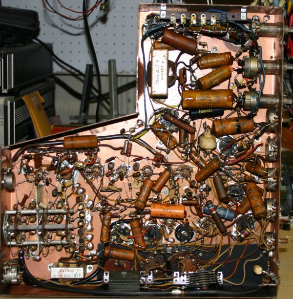
I Recently decided I wanted to undertake the restoration of an antique television, the older the better. So I wouldn't be stuck with something too big to display or move around easily, I determined I should get something small, a 1940's 7" model ideally.finally found one that looked promising on eBay which sold for a reasonable amount so I bought it. Below are some photos before the restoration. I did disassembly, basic cleaning and tested all the tubes. Two of the CRT pins stayed in the socket when I removed it. On inspection the wires emerging from the envelop were intact, the old solder joint had simply failed. Several more of the CRT Pins were loose. I removed the two errant pins from the socket, cleaned out the old solder and reattached them to the CRT wires. I then added a drop of super glue at the base of each pin, and carefully cleaned the socket - which shows some evidence of old arcing. On inspection of the chassis it is apparent that this set was repaired, probably in the 1960's. A couple of the paper capacitors were replaced as well as 2 resistors in the horizontal output section. It also appears that all 3 large filter capacitors and the ballast "tube" were replaced. Because these filters would still be 30 or more years old I have decided to bypass them under chassis in the usual fashion with new capacitors, as well as replace all the old paper capacitors - many of which show evidence of melting wax drips. All this will be done before first power up.
|
|
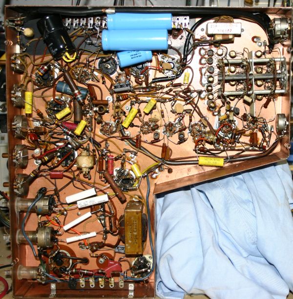
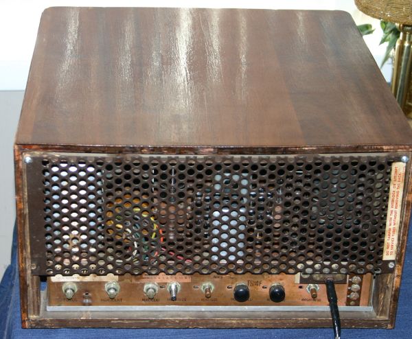
Original chassis underside showing evidence of prior repairs |
|
|
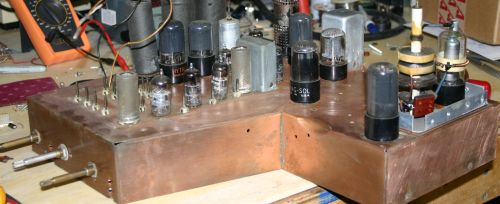
chassis top after cleaning |
You can clearly see the drips from the high voltage capacitors at the top in the horizontal output section. You can also see the "new" black beauty under the large capacitor at top. You can also see a replacement cap nearer the bottom. Although its not visible here, one of the wires on a filter section is attached well mechanically but not soldered, hence my conclusion it was replaced. Several solder joints at top look very bad and are obviously cold. You can see at bottom I have removed the bolts from the selenium rectifiers and mounted a pair of barrier strips to hold the new filter caps and diodes.
|
|
|
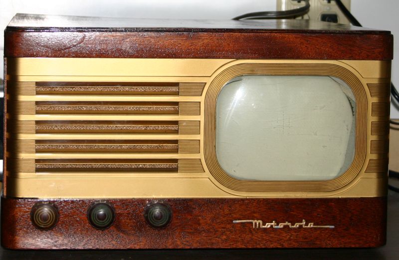
Original case |
|
|
|
CRT after cleaning |
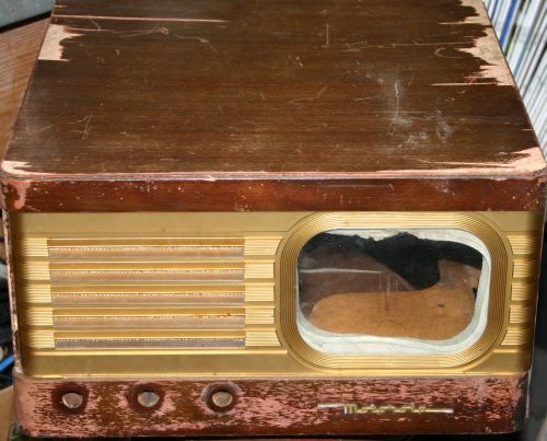
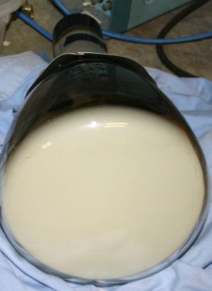
The case has seen better days, but is intact, including the back cover. It should be possible to replace the top veneer and refinish the front. The CRT gasket was melted at the top as you can see. Quite a bit of careful scraping was needed to detach it from the CRT.
Here are some pictures of the restoration - in progress.
 |
|
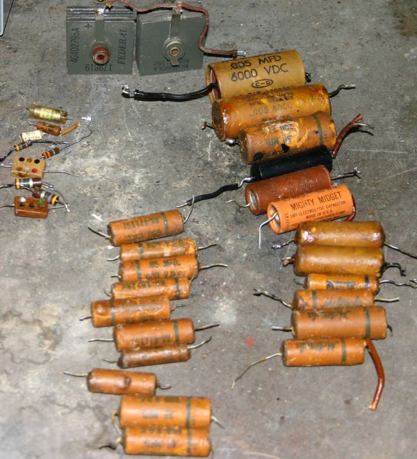
Parts replaced initially - mostly wax caps |
 |
|
Chassis after re-capping, and some repair |
And here is the first picture - YAY the CRT works.
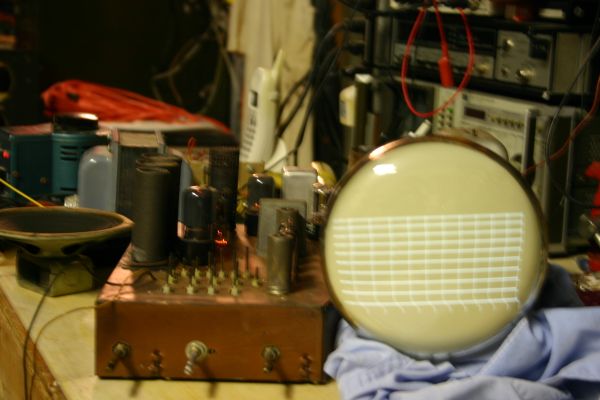
To get to this point some repairs were required in addition to the initial replacement of all the paper/wax caps.The video detector used an early 1N34 - which was open, surprisingly, at least to me, the precision NPO caps in the detector were also open. Several of the plastic encapsulated mica caps in the vertical oscillator/amplifier were shorted. Several high value resistors in the same circuit were open. Part of this may have been because the replaced .05/6KV black beauty capacitor from the earlier repair was shorted. Since the deflection plates are floating near the full 2nd anode potential (about 5 KV) this caused some serious arcing, and surely accounts for at least a couple of the failures. However, resistors and capacitors far away from the output tube, in the oscillator were also bad. Looking at the distortion in the test pattern I would say several resistors, and possibly caps which have not been replaced have changed value significantly. The front end RF and IF components appear to be ok. This picture (and sound) are produced via an RF signal at the input.Here is a schematic of a similar - though not quite identical chassis. It took some looking to find this on a German website of a restorer of old TV's over there. It is embedded at full size, but displayed smaller.

Finally finished today. Had to replace several tubes, and more resistors before it was all done. Below are the photos of the final chassis bottom, the assembled and fully refinished case
|
|
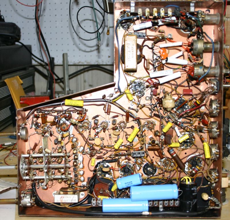
Chassis after all parts replacements |
|
|
Re-assembled from the back |
|
|
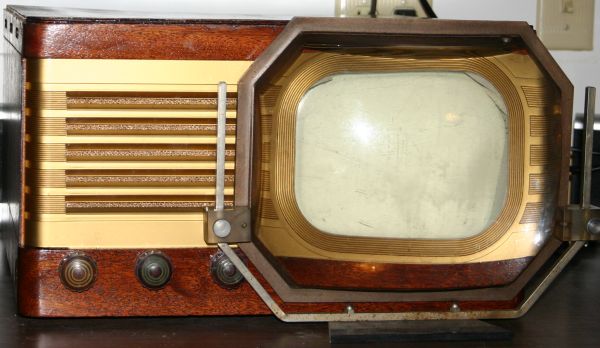
After re-assembly from the front. |
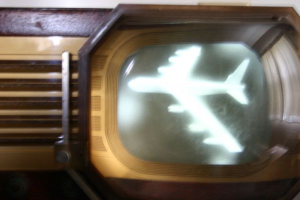
On the whole its working well. I have ordered replacements for 2 more of the tubes which show marginal emissions on my tube tester, but the television works and survived a several hour burn in. Here finally, is a photo of the picture as seen through the original water filled lens accessory and a photo of the set with the lens positioned for viewing. The picture looks much better than the photo would lead you to believe - it is quite difficult to photograph a live, moving picture on a television of this vintage. In person the picture is quite good for an analog, vacuum tube based television of any age. Now I only need to find gold colored transfer letters to restore the labels on the front panel controls.
 |
|
A picture displayed through the lens |
 |
|
Front with the lens in place |